Video link:
Bilibili video – Function demonstration and introduction
Project Overview
I previously obtained a CRPS server power supply from a friend, but I was frustrated by the fact that most existing open-source solutions were based on CSPS power supply solutions. Therefore, I wanted to design an intelligent CRPS power acquisition board based on the ESP32-S3 microcontroller, which would also support physical button control and web interface control.
Project features
This design is based on the ESP32-S3-WROOM-1-N16R8 module, enabling control of power supply for a CRPS (Customer Relationship Management System) server that can connect to the home network.
Regarding output, it supports two XT30 outputs and one XT60 output.
Perform grid connection operation using ESPTouch. After successful grid connection, access the local network IP address of the energy harvesting board to enter the web interface.
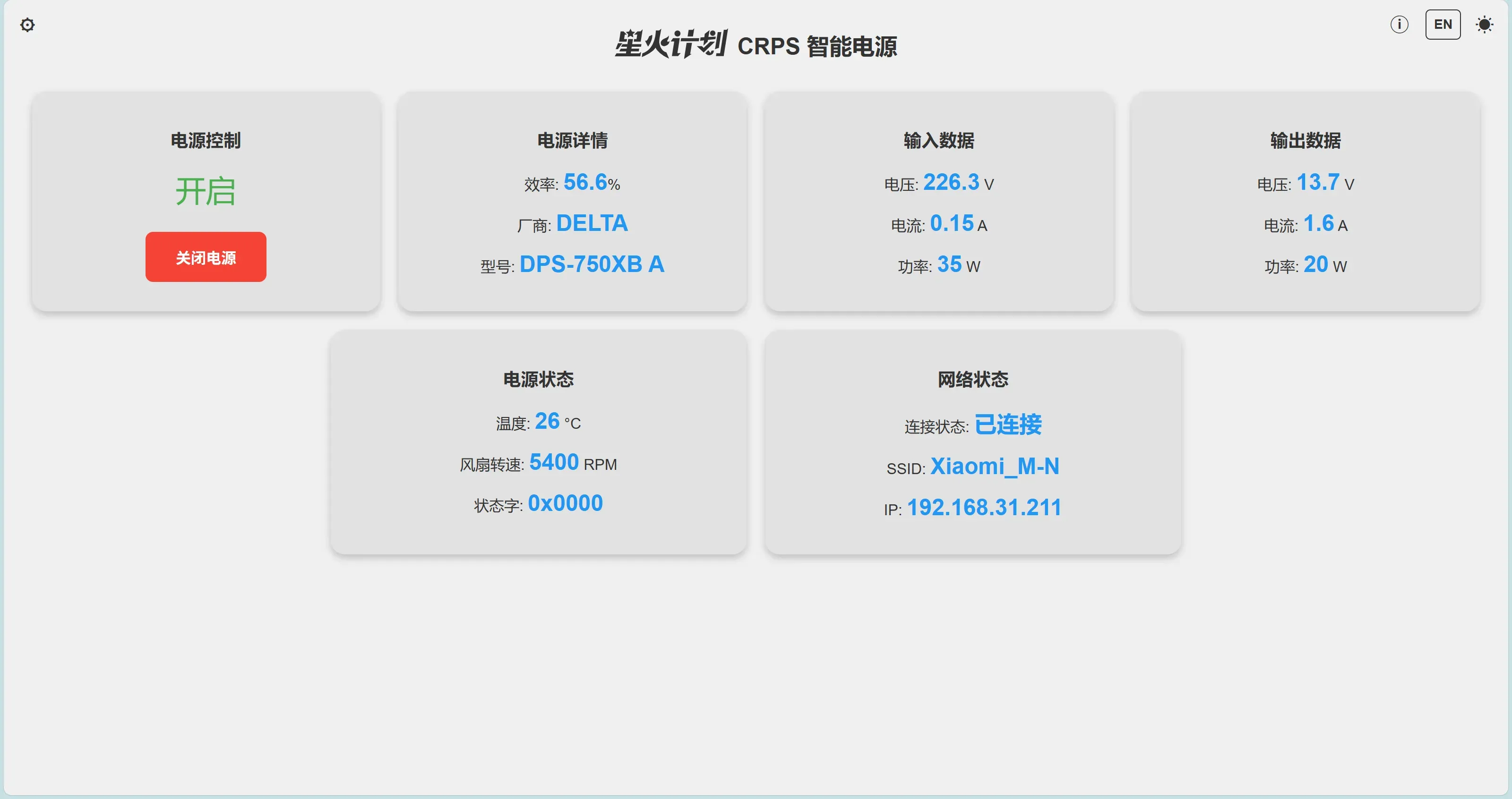
The web interface supports switching between power on/off states and real-time display of various power status, as well as switching between English and Chinese languages and dark mode.
Click the gear icon in the top-left corner of the main interface to access the settings interface.
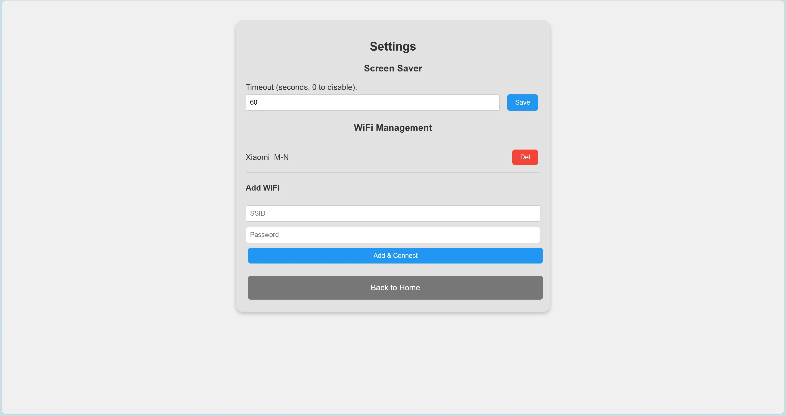
The settings interface allows you to set the screen saver start time, with a default of 60 seconds without physical button operation; it also allows you to manage saved Wi-Fi networks or add other Wi-Fi networks, and only supports the 2.4 GHz frequency band.
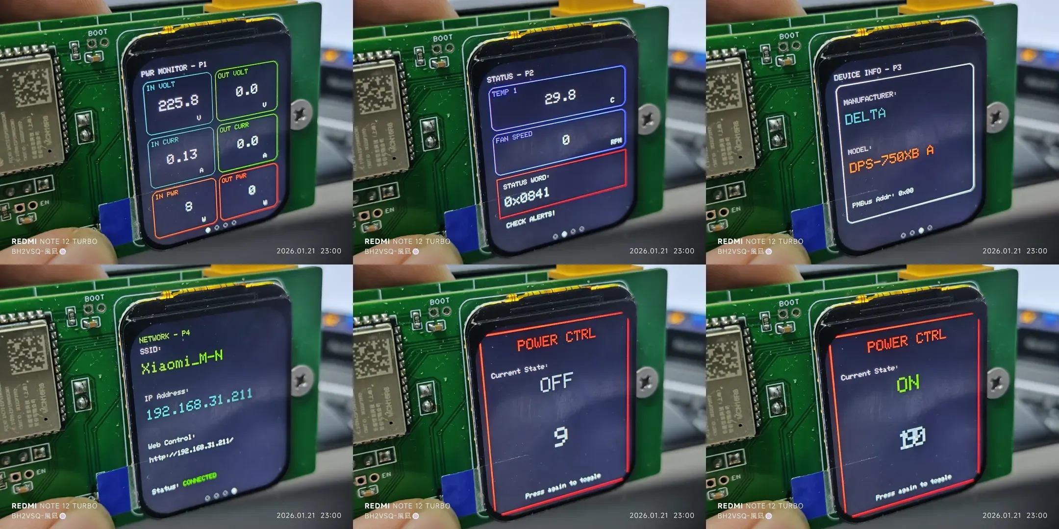
The screen on the control panel also displays the real-time power status. Pressing the physical button will bring up a switch interface for changing the power state. If the button is pressed within 10 seconds, the switch state will be changed. If no action is taken within 10 seconds, it will automatically revert to the information display.
Project parameters
The power interface section uses a Yokopo 50p connector.
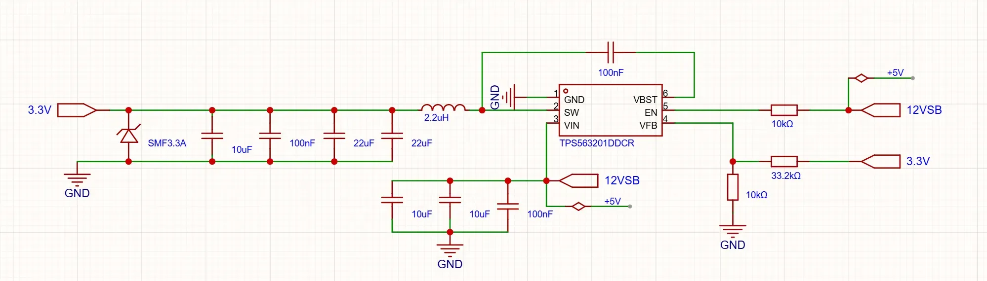
The power supply section of the ESP32 uses the TPS563201DDCR to step down a 12V or 5V input voltage to 3.3V for powering the device.
The onboard Type-C port can be used for both power supply and programming (flashing) of the ESP32.
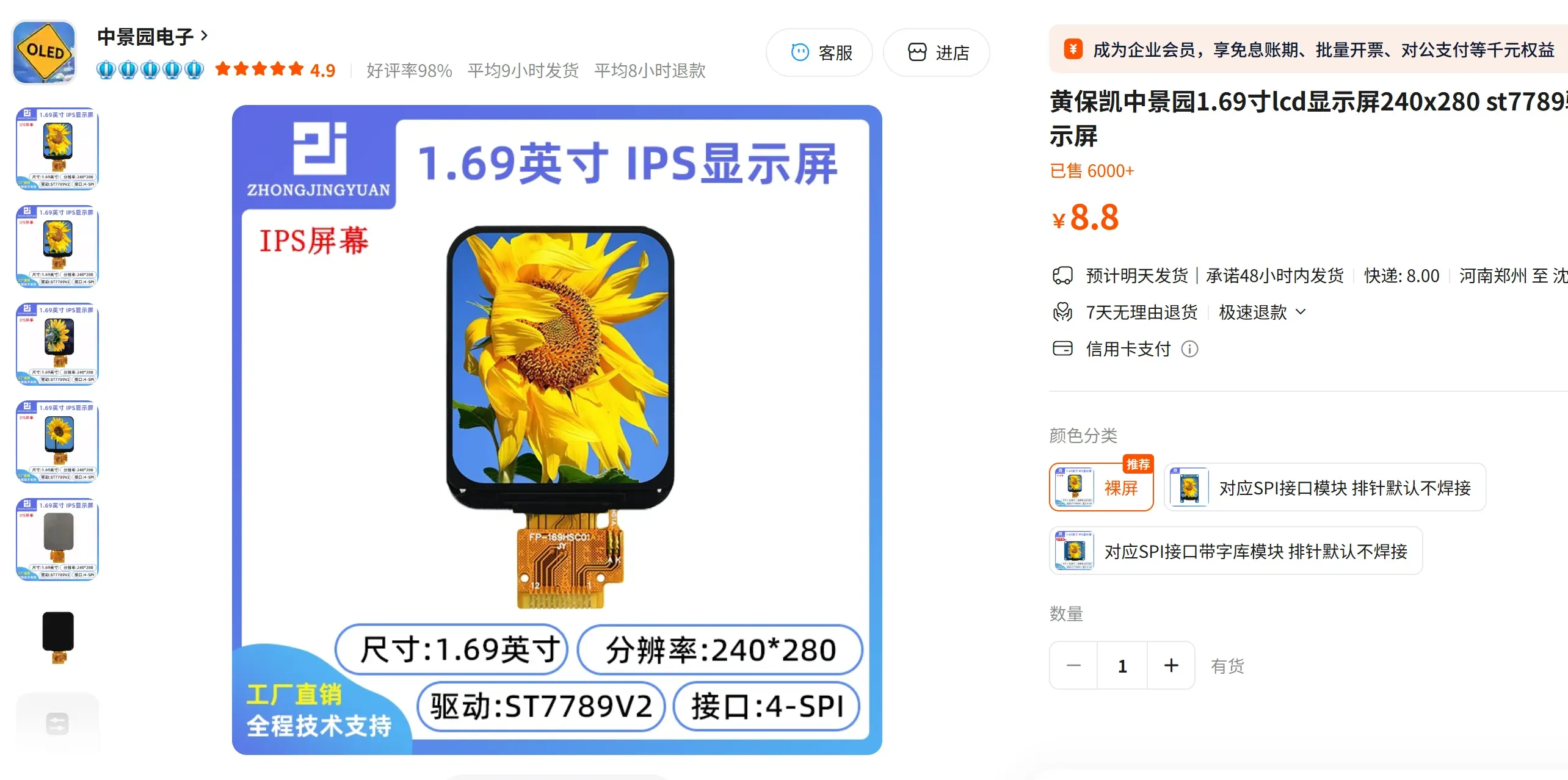
The screen uses the ST7789 module with a 1.69-inch display area.
Fundamental Analysis (Hardware Specifications)
The power switch control uses a single BSS138 component.

For the power section, this project will short-circuit the 5V and VSB terminals. This ensures that the ESP32 can be powered normally whether it draws power from the main power supply or via USB.
Please note: They cannot be powered simultaneously, otherwise it will damage the equipment.
Important notes
1. USB power and power supply cannot be used simultaneously, as this will damage the device. When programming, you must disconnect the power supply and use an external power source.
2. The new ESP32-S3 module does not have any pre-programmed code and requires entering programming mode to flash correctly. After power on, you need to first short the BOOT pin, then the EN pin, followed by releasing the EN pin, and finally releasing the BOOT pin. These two sets of pins have pre-reserved jumper positions on the PCB.
Assembly process
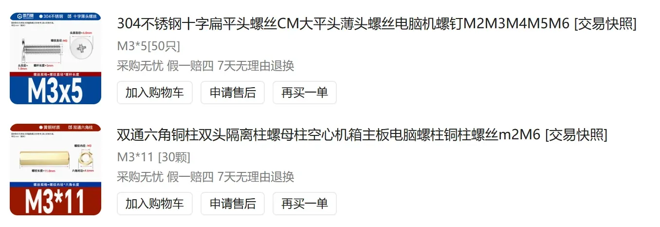
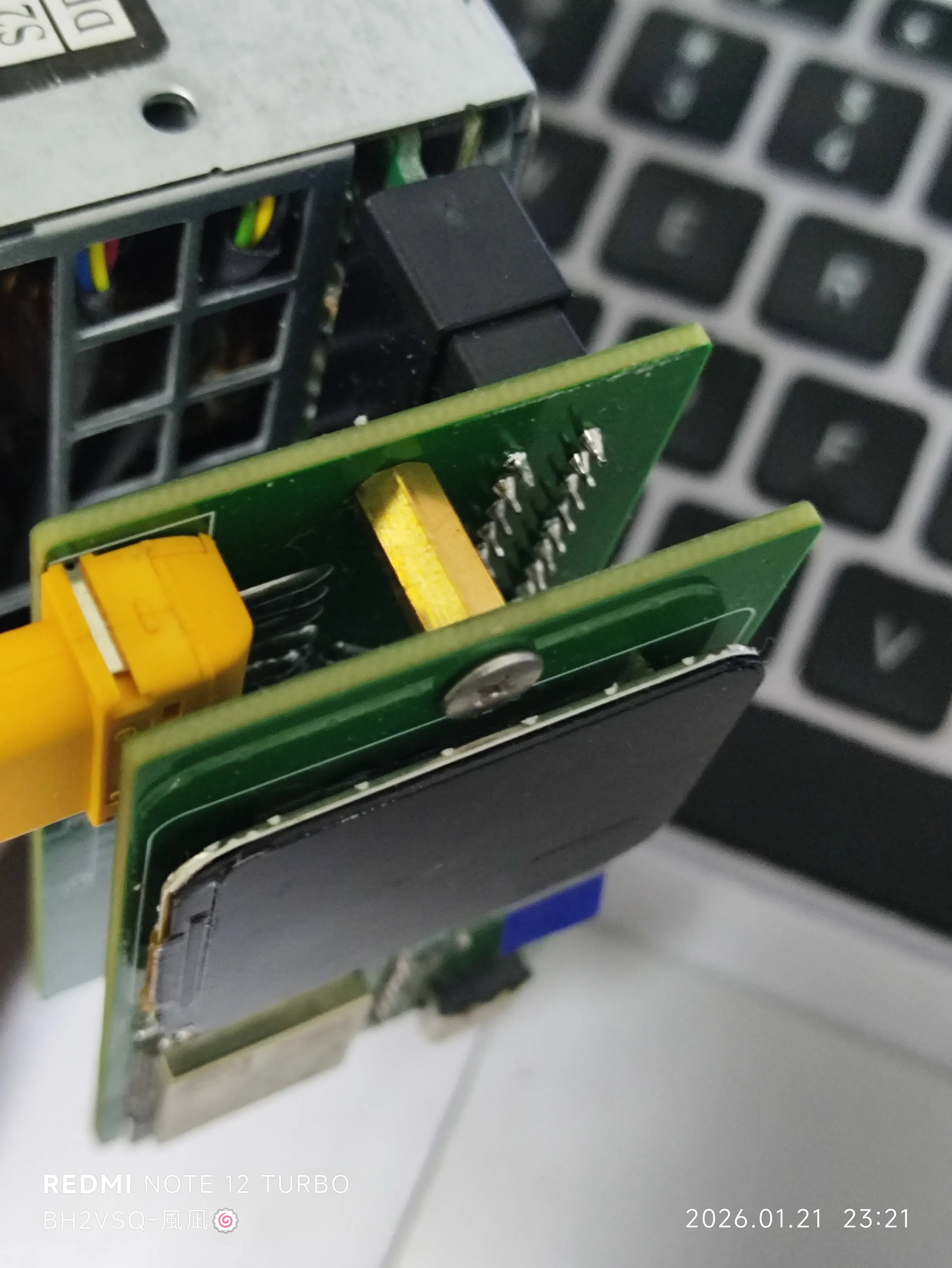
This project uses a modular design: the power interface and LDO are on one PCB, the ESP32 control board is on another PCB, and the electrical connections between the two PCBs are made using 2.54mm pitch header pins. Mechanical connections require purchasing copper pillars and screws as shown in the diagram.
The assembly effect is as follows: fixed with two screws and one copper column.
Project address
The exterior hasn't been painted yet; I'll open it up after I finish painting it.


 闽ICP备2021006864号-7
 闽公网安备35020602002794号