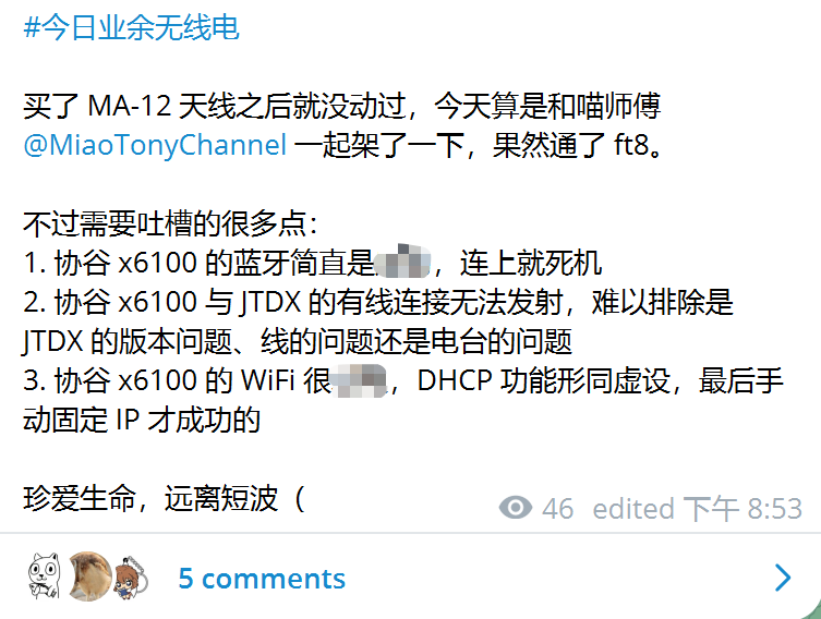
Due to my social anxiety and lack of experience with direct voice communication, I didn't engage in much contact before taking the B license exam. After obtaining the B license, I became a "company slave," and the complex electromagnetic environment at my living location made it difficult to use any equipment I purchased. It wasn't until recently, encouraged by my junior, that I started experimenting with FT8 communication, and I encountered the following situation:

The author was frustrated with the limitations of the original firmware for the XieGu X6100, and also lacked the funds and space to purchase new equipment. Therefore, they were looking for ways to improve the XieGu X6100 firmware. After some searching, the author found an alternative firmware for the XieGu X6100 and was excited to explore its features. The author hoped to take advantage of this opportunity to learn about basic amateur radio knowledge and equipment usage. This article attempts to briefly introduce the alternative firmware and its usage methods.
[Attention] Important reminder before reading.
- Due to my limited understanding of the various features of the original X6100 firmware, I may inadvertently repeat descriptions of functionalities that are consistent with those found in the original firmware when introducing alternative firmware.
- This is an article that combines instructions on how to use a product with some criticism. If you find it unsuitable, please close this page.
Introduction
The initial firmware replacement for the XieGu X6100 was provided by R1CBU Development, based onIntroduction, this firmware "is designed to build a Linux kernel and operating system for the XieGu X6100, without needing to copy files from the vendor's kernel." In updating Version v0.20.0After releasing the firmware, the author became disillusioned and stopped developing further.
I am no longer satisfied with the quality of this transceiver. I am unhappy with devices developed using closed-source code. I don't want to waste any more time. I have decided to halt development on the XieGu X6100 firmware and develop my own transceiver to address these issues. If XieGu suddenly becomes interested in continuing my work, I would be willing to communicate with them.
After that,R2RFE CompletedSubsequent development workand continue to release New version。
Usage
The usage is very simple; just download the file provided by the author. sdcard.img, using rufus Burn the firmware to a MicroSD card, then insert it into the machine and power it on to enter the alternative firmware.
Features
Besides the physical buttons, two functions are most commonly used by users: replacing the firmware with the X6100.Graphical user interfaceAndWeb serverThe features will be introduced separately in the following sections.
If you would like to watch a video tutorial demonstrating the features, I plan to create a demo video.
Physical buttons

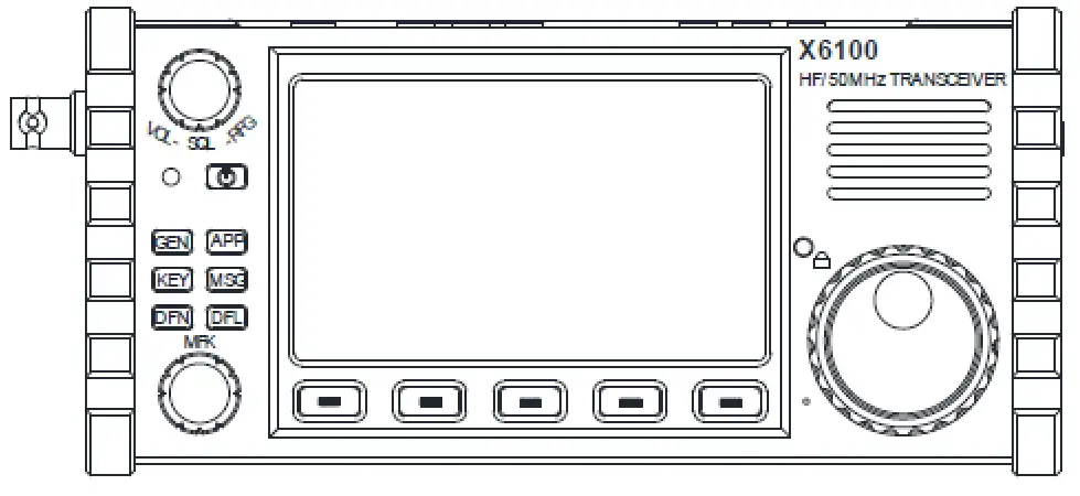
The X6100 firmware replacement has made some customizations to the buttons on the left side of the front panel. However, R1CBU manualThe existing description is already partially available, but it is somewhat outdated. The following sections will modify and add descriptions based on his manual:
VOL-SQL-RFG Knob
- The button can be used to lock or unlock the current function.
- When rotating while locking the current function, you can switch the value of the current function.
- When rotating to unlock the current function, you can switch between different functions:
- Volume: Volume
- RF Gain: Radio frequency gain(0-100)
- Filter Low: Controls the lower frequency of the demodulation digital filter.
- Filter High: Controls the upper limit frequency of the demodulation digital filter.
- Power: Transmitting power
- H-MIC gain: Handheld microphone gain
- Return to Volume;
- The rotary button can be used to adjust the functions described above.
MFK knob
- The button can be used to lock or unlock the current function.
- When rotating while locking the current function, you can switch the value of the current function.
- When rotating to unlock the current function, you can switch between different functions:
- Spectrum zoom: Control the width of the frequency band and waterfall display.
- Spectrum beta: I don't understand.
- Peak Hold: The duration for which the peak value of the spectrum is displayed.
- Peak Speed: Maximum speed
GEN button
- It includes several menus.
- Pressing and holding the button will take a screenshot and save it to the SD card.
- The "Tap Button" will switch to the following menu:
- VOL Menu: Use the VOL-SQL-RFG knob to modify the selected function.
- Vol. 1/4
- Volume: Volume
- Squelch: Noise level
- RF Gain: Radio frequency gain(0-100)
- TX Power: Transmission power
- Volume 2 / 4
- Filter low: Control the lower frequency of the demodulation digital filter.
- Filter high: Control the lower frequency of the demodulation digital filter.
- BW Filter
- SP mode: Speaker mode - I don't understand what this means.
- Volume 3/4
- MIC Sel: Microphone Selection – Allows you to select either the handheld microphone or use the built-in microphone.
- H-Mic gain: Handheld microphone gain
- I-MIC gain: Built-in microphone gain
- I don't understand what "Moni lebel" means.
- VOL 4/4: This level of menu appears to be generated by radio voice synthesis, and is RHVoice Regarding this, but I haven't yet understood how to use it.
- Voice: Choose tone/sound color
- Voice Rate: Audio rate
- Voice Pitch: I don't understand.
- Voice Volume: Sound volume
- MFK Menu: Use the MFK knob to modify the selected function.
- MFK 1/4
- Minimum Level: The minimum level displayed in spectrum and waterfall charts.
- Maximum Level: The maximum level displayed in both the spectrum and waterfall charts.
- Spectrum Zoom: Control the frequency width of the spectrum and waterfall display.
- Spectrum Beta: I don't understand.
- MFK 2/4
- Spectrum Fill: Spectrum fill color
- Spectrum Peak: Set spectrum peak value
- Peak Hold: The duration for which the peak value of the spectrum is displayed.
- Peak Speed: Maximum speed
- MFK 3/4
- Charger: Controls the state of the battery charger. If I'm not mistaken, its values correspond to:
- On: Charging the battery
- Off: Directly use the charger, without charging the battery.
- Shadow: I don't understand, but according toThis articleIt's speculated that it only charges when the battery is not fully charged.
- Antenna: I'm not sure what it controls; the adjustment range is from 1 to 5.
- RIT: Receiver Incremental Tuning
- XIT: Transmitter incremental tuning
- MFK 4/4
- AGC hang: The time AGC waited before making a change.
- AGC knee: The value of the AGC gain slope change.
- AGC slope: The value of the AGC slope.
- MEM Menu
- There are two pages with a total of 8 storage locations, which can be used to store frequencies and modes.
- The short-press button allows for quick loading of saved frequencies, while the long-press button saves the current frequency setting.
APP button
- Includes a three-level menu.
- APP 1 of 3
- RTTY: Initiate RTTY mode
- FT8: Start FT8 mode
- SWR Scan: Perform a VSWR scan on the frequency band.
- GPS: Update time and location information through an external GPS device.
- Application 2/3
- Recorder: Recording device
- QTH: The geographical location information used for setting the FT8 mode.
- Callsign: Set the callsign to be used in FT8 mode.
- Settings: Machine settings interface
- App 3/3
- Wi-Fi: Set Wi-Fi information
KEY button
It appears to be designed specifically for CW mode, and as I don't currently have any plans to use CW, I've skipped the introduction of this button.
MSG button
The recorded message can be transmitted at the current frequency, with no further explanation needed.
DFN button
- DFN, Digital Noise Filtering
- Includes a three-level menu.
- DFN 1/3
- DNF: Is DNF enabled?
- DNF frequency: DNF control center frequency
- DNF width: DNF control filter width
- DFN 2/3
- Note: Noise Blocker – Is the noise blocker enabled?
- NB level: Noise suppression level
- NB width: Noise suppression circuit width
- DFN 3/3
- NR: Noise Reduction, whether noise reduction is enabled
- NR Level: Set noise reduction level
Graphical user interface
This section will provide a brief overview of the general functions of the graphical interfaces that I commonly use. Since I am currently only using the FT8 function, the following sections will primarily focus on the graphical interface for the FT8 function.
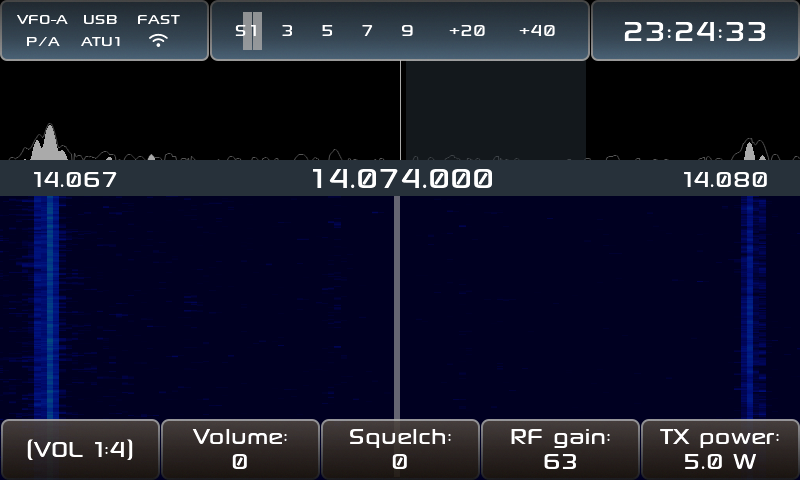
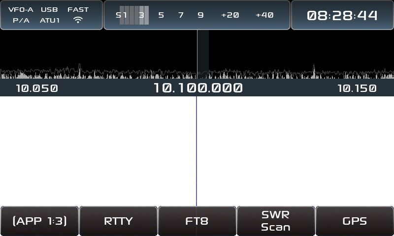
After starting the radio, the default interface (version 0.28.0) looks like this:

The status bar at the top is divided into three sections:
- The status bar on the left side, from left to right and top to bottom, shows:
- VFO memory
- Communication mode
- AGC mode
- Pre-amp booster status
- Automatic antenna tuner status
- Wi-Fi status
- The middle status bar indicates signal strength; during transmission, it displays transmit power and antenna VSWR (Voltage Standing Wave Ratio).
- The status bar on the right side will display the time and battery level/voltage.
The most prominent features on the screen are the spectrum and waterfall chart, which can be controlled using the largest knob on the right to adjust the frequency.
The functionality settings described below are controlled by the [[#physical buttons]] mentioned earlier, making them very simple and easy to understand.
If we need to use the FT8 function, first adjust the time so that the error with real-time is no more than 1 second. Then click the app button twice to set the QTH and callsign respectively, and then click the app button again to enter FT8 mode and start scanning.
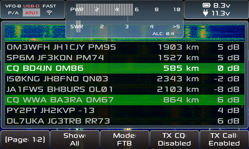
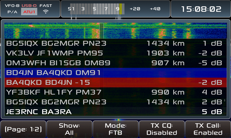
Here, we demonstrate the process of using the X6100 firmware replacement to perform FT8, taking as an example the communication between BD4JN's Jinan Yellow River amateur radio collective station. As shown in the figure, the information on the left is the FT8 information parsed by the firmware, the information in the middle is the distance between the two parties after setting the QTH, and the information on the right is the signal strength. The CQ call that initiated the contact is marked in green.
On the screen, we see that BD4JN has initiated a CQ. At this point, we rotate the MFK button to the information "CQ BD4JN OM86", press the MFK button, and the firmware will initiate the call in the next cycle:

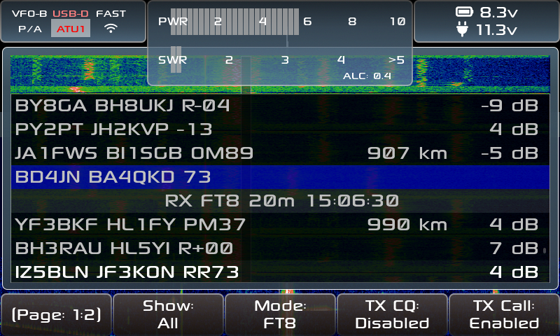
On the screen, we can see the antenna and standing wave ratio at the time of transmission. After the call ends, our call information will be marked in blue, and the firmware will wait for the next cycle to receive a response. If there is a response from the other end, that call information will be marked in red:

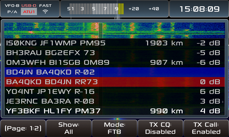
After that, you can continue to communicate until the other party sends RR73:

At this point, the firmware will save this communication and send "73 End:"

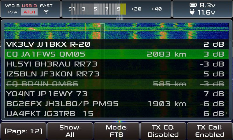
Once the communication is complete, this call sign will be recorded in the database of the previously contacted radio station. The next time the radio station calls, a line will be marked on its frequency to avoid repeated calls:

Web server
Once connected to Wi-Fi, you can access the web server by entering the IP address of the X6100 on other devices within the same network segment. The current web server has the following main functions:

The following will be introduced one by one.
Bands
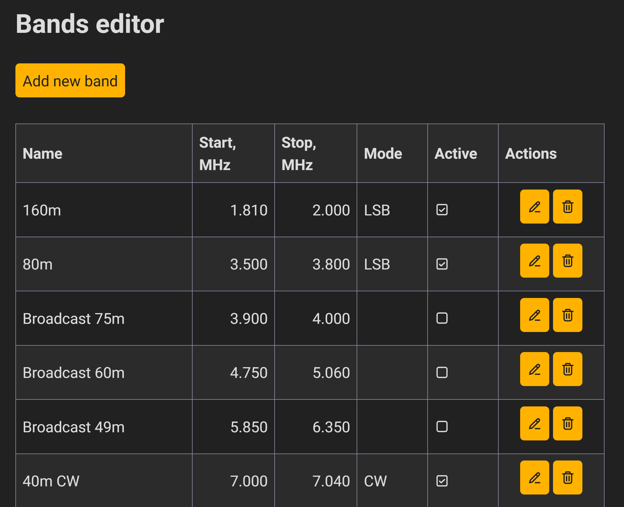
This feature is a band editor for non-digital modes, and includes some default values:

When using an alternative firmware, if you use the up and down buttons on the device to switch bands in the default band mode, the device will automatically switch to the selected band. The author has also carefully set the corresponding spectrum width for different modes, making it more convenient to use.
If needed, you can add the corresponding frequency band and save it, after which it will automatically switch as described in the previous section.
Digital modes
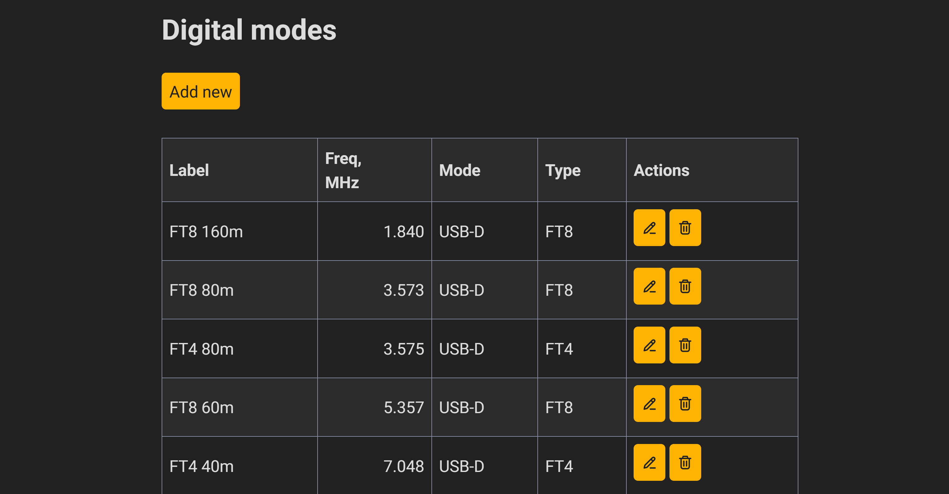
This feature is a frequency editor for digital modes, primarily supporting FT8 and FT4 modes, and also allows adding new frequencies.

When using an alternative firmware, if you use the up and down buttons on the device to switch frequency bands in digital mode, the device will automatically switch to the specified frequency.
If needed, you can add the corresponding frequency and mode, save it, and then switch automatically as described in the previous section.
File browser
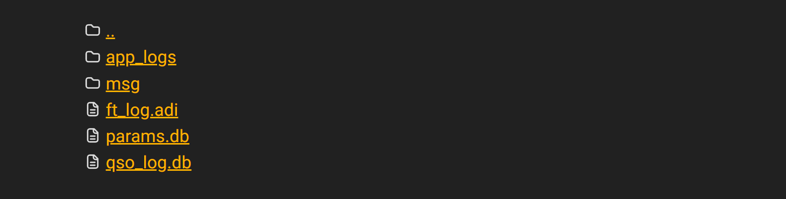
File manager: Download and save logs, data, screenshots, etc. from Tonglian.

ft_log.adi: FT8/FT4 logging, which can be uploaded to LoTW or qrz.com;
params.db: Some parameter information should not be overwritten during cross-version updates of the x6100_gui, as this may lead to unexpected issues.
qso_log.db: This saves previously used callsigns, so you don't need to call when using FT8/FT4 again.
Time Editor
Sometimes, there may be a situation where the broadcast time and actual time do not match, which can easily occur:
- It's possible that I accidentally tapped the time synchronization option in the FT8 menu.
- It might be possible to start the machine and begin using FT8 even without an internet connection.
- It's possible that the NTP server cannot be reached.
In this situation, the ntpd within the system cannot provide timely time synchronization, and attempting to manually adjust the time is also detrimental to eye protection. I saw someone in the issues section who also wanted to be able toPerforming time synchronization on a web serverTherefore, I have successfully implemented this feature.
Currently, the following time synchronization methods are supported:
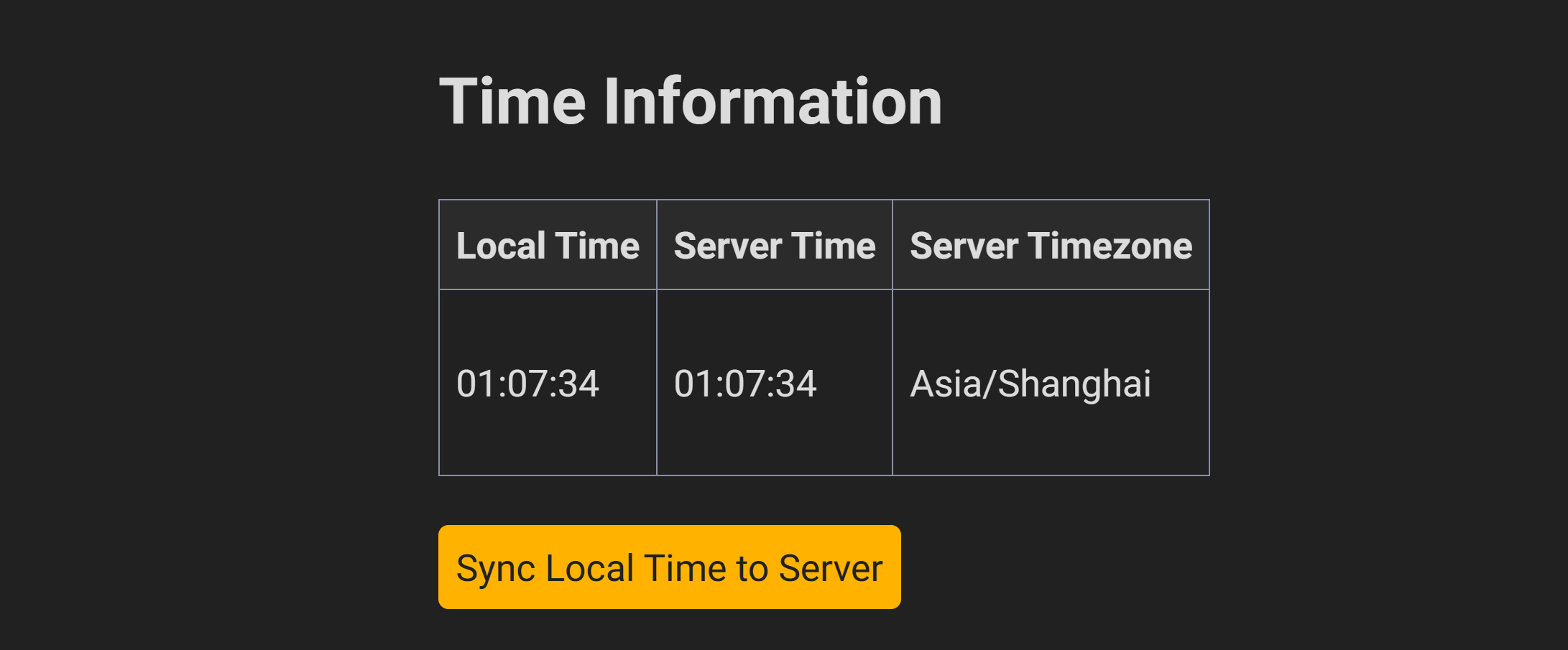
Synchronize local time
When loading this page, the current radio time/time zone and the time of access to the radio device are automatically obtained. We can synchronize the local time with the server. This synchronization method will be slower than normal time by tens or hundreds of milliseconds.

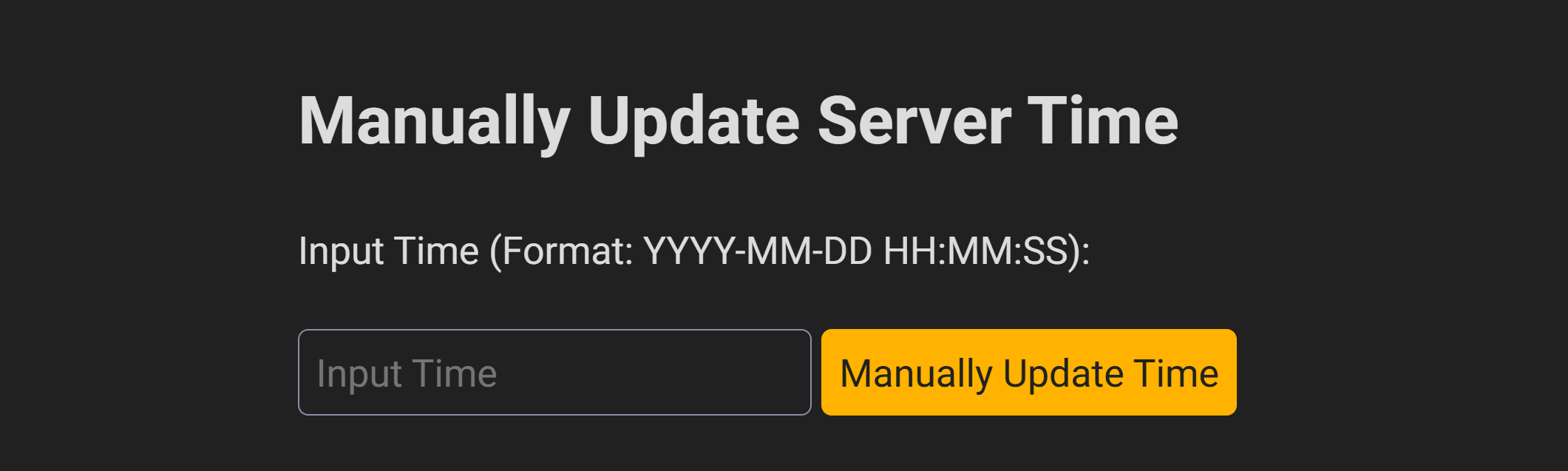
Manual update time
This method is similar to updating the time in a radio setting. Since I'm quite lazy, I only provided a direct string input method for updating. When you click "Update Time" when it's 1 second ahead of the normal time, it will align more accurately with the normal time.

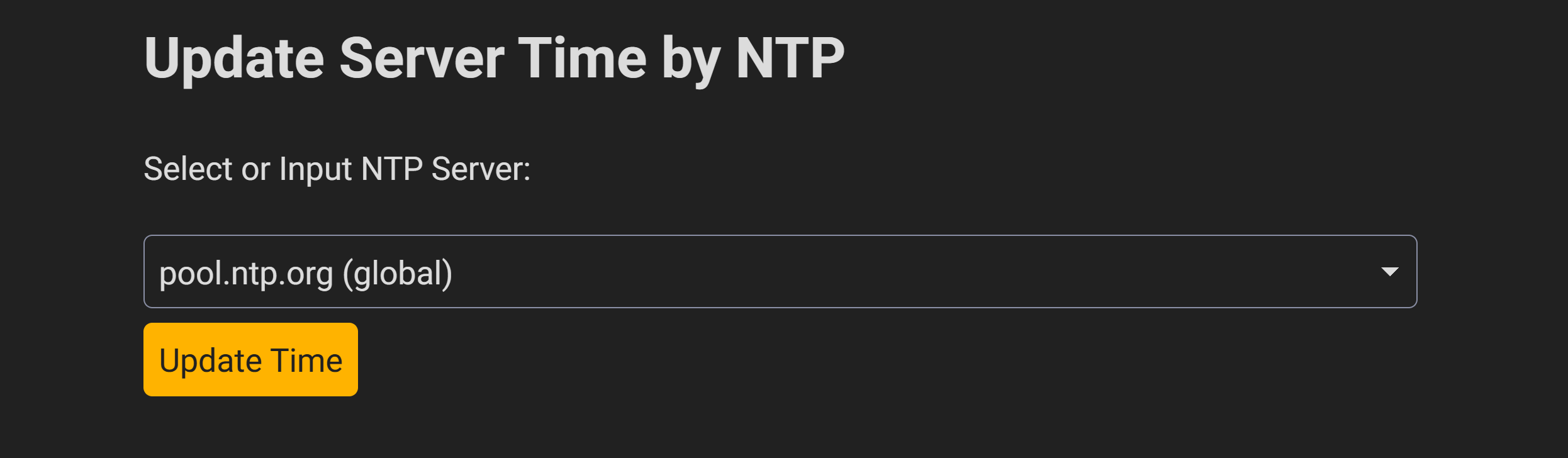
Update time using an NTP server
Although devices automatically synchronize time via NTP after connecting to Wi-Fi, the NTP server may not be accessible. We also want to manually set the NTP server address. Here are some common NTP servers that we can use, and we can also manually enter the address of the NTP server.

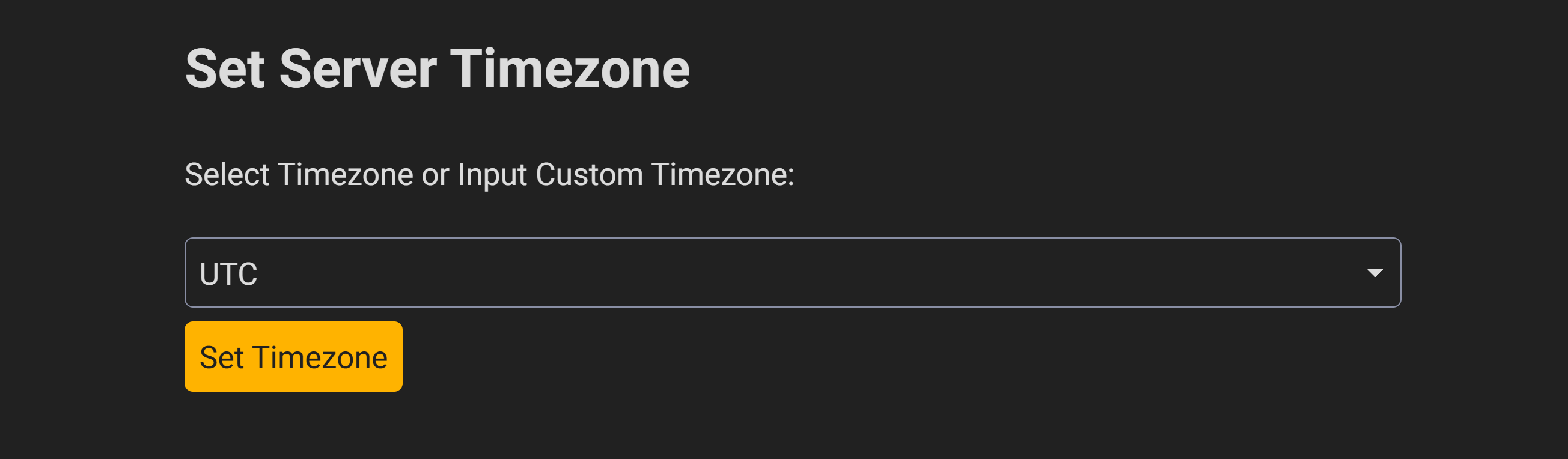
Update time zone
The default system time is UTC, which can be changed to match your local time.RequirementsTime zone.

Other features
Once connected to Wi-Fi, you can SSH into the target machine. The default username and password are root/123. (The native X6100 system also works this way, but without DHCP, setting the IP address via buttons is very cumbersome.)
Compilation and Customization
[!Attention] This is not a complete usage tutorial.
The author does not have experience with buildroot, so this article may not be suitable for experienced or expert users of buildroot. This article aims to quickly get started with the various functions of the XieGu X6100 firmware replacement and compile the target modules as quickly as possible.
[!] Warning: Proceed with caution when flashing.
Flashing (updating) software may result in data loss or irreversible damage to the device. The code examples provided in this article are for reference only, and the author is not responsible if any damage occurs after execution.
Compile the entire firmware.
If you need to compile the entire firmware, please do so in the following steps: AetherX6100Buildroot Next to be executed:
./br_config.sh
cd build
make
Upon successful compilation, it will be build/images Create `sdcard.img` in the directory.
Custom application
After compilation, we are interested in the directory structure of the X6100 replacement firmware, specifically focusing on:
$ tree -L 2 ./
./
├── ...
├── br2_external
│ ├── ...
│ ├── board # Board information
│ ├── ...
│ └── package # Applications
├── br_config.sh
├── build
│ ├── ...
│ ├── images # Contains image files
│ ├── ...
│ └── target # Target
└── ...
If we want to customize existing features, we can first clone the desired feature locally and then modify it. br2_external/package/<package name>/ Corresponding to the above .mk Content of the file:
# <package name>_VERSION = v0.0.2 # Comment out this line
<package name>_SITE = <package path> # Pointing to a local path
<package name>_SITE_METHOD = local # Change to local
After modifying the code, simply do the following: build Execute in the directory:
make <Package name>-reconfigure
Among them <package name> For the name of the target application. build/target/ I found new code below.
For example, x6100\_gui is located at ./target/usr/sbin/x6100_gui, x6100\_webserver located at ./target/usr/lib/python3.11/site-packages/x6100_webserver/。
Theoretically, it's not necessary to reflash; you only need to SSH into the machine, perform a complete replacement, and then restart the service or the machine.
Adding functionality to the firmware
While developing some small features, I gradually came to understand the principles of Buildroot. Although I had several functionalities in mind, I was unable to successfully implement them (some were only partially completed and abandoned). This record serves as a documentation of that process.
While reviewingI have written a simple remote controller based on the losehu firmware for the UV-K5/K6.After this article, I attempted to add a WebSocket-based graphical interface for viewing and managing the web server, trying to use Pillow and WebSockets for image processing and communication between the front end and back end. To install these two packages, I needed to: AetherX6100Buildroot/br2_external/configs/X6100_defconfig Add parameters:
BR2_PACKAGE_PYTHON3_SSL=yes
BR2_PACKAGE_PYTHON3_ZLIB=yes
BR2_PACKAGE_PYTHON_WEBSOCKETS=yes
BR2_PACKAGE_PYTHON3_PYEXPAT=yes
BR2_PACKAGE_PYTHON_PILLOW=yes
This can then be used within the firmware.
To enable remote interface viewing and function control, it is necessary to take screenshots at regular intervals and send them to the front-end. The screen resolution of the X6100 is 800x480. If PNG images are transmitted directly, a single graphical file would be approximately 500KB, which feels quite large. Therefore, I considered compressing the screenshots into JPG or webp format before transmitting them. However, this presented two problems:
If compressed to JPG, issues may arise due to incompatible Pillow versions and the mismatch between the required libjpeg version (Pillow needs libjpeg9+) and the libjpeg-turbo generated by the firmware (which is libjpeg8).
If compressed to WebP format, you need to add the WebP library during firmware compilation:
BR2_PACKAGE_WEBP = y
However, even with this workaround, Pillow still couldn't find the installed `webp` library during runtime, and the reason for this remains unknown.
If the first two problems are relatively easy to solve, and we can't find another way, then the last problem is one that I am truly at a loss for. As everyone knows, on Linux, we can obtain information about the current screen by reading the framebuffer. Therefore, I have simply implemented a logic for reading the buffer:
with open(FRAMEBUFFER_DEVICE, "rb") as fb:
raw_data = fb.read(SCREEN_WIDTH * SCREEN_HEIGHT * BPP)
The screenshots I read looked like this:

That means the screenshots I'm seeing here don't include waterfall charts. This is quite perplexing, so I first looked for built-in screenshot functionality within the firmware, which is located at: x6100_gui/src/screenshot.c:
void screenshot_take() {
uint32_t buf_size = lv_snapshot_buf_size_needed(lv_scr_act(), LV_IMG_CF_TRUE_COLOR_ALPHA);
buf = (uint8_t *) malloc(buf_size);
lv_snapshot_take_to_buf(lv_scr_act(), LV_IMG_CF_TRUE_COLOR_ALPHA, &snapshot, buf, buf_size);
pthread_t thread;
pthread_create(&thread, NULL, screenshot_thread, NULL);
pthread_detach(thread);
}
In simple terms, LVGL itself provides a screenshot API. When developing firmware based on LVGL, you only need to call this API. While knowing the solution for the firmware doesn't solve the problem I encountered, I didn't have enough time to thoroughly understand the implementation principles of the API. Therefore, I had to temporarily put aside the idea of implementing it. If any HAM is interested, please let me know what I should do next.
In summary
When using native firmware on FT8, you may encounter various issues, including but not limited to:
- Problems connecting to JTDX and WSJT-X
- Some people have also raised concerns about potential issues when using the system in other contexts.
- The problem is that there's no DHCP server, so I have to manually configure static IPs.
For alternative firmware, FT8 can be used for communication, but there are also some additional issues:
- Compared to WSJT-X, the built-in FT8 can decode a smaller number of messages and may produce inconsistent results.
- However, alternative firmware can also theoretically connect to WSJT-X.
- There are some issues with the implementation of the FT8 functionality built-in.
- In some cases, location information of the other party is not recorded, and the specific reason for this has not yet been determined.
For this machine, it's a relatively affordable and suitable radio for new B category users. A small package can hold the radio, NanoVNA, power bank, and a 12V coax cable, allowing you to set it up almost anywhere. As an SDR radio, it has a decent number of ports, but the firmware still has many immature aspects, so it's only barely usable.
Regarding the X6100, in HamCQ AndForeign forumsThere have been many discussions on this topic; interested readers can find relevant articles in the forum.
[Success] Experience of updating firmware
Before upgrading the firmware, I used FT8CN to control the X6100 and encountered many frustrating issues. Ultimately, I only managed to connect with 3 stations, and only twice were the connections successful (both sides confirmed on LoTW/QRZ). However, after upgrading the firmware and using the built-in FT8 functionality, I was able to achieve approximately 20 successful contacts within an hour, which significantly reduced my frustration.
Future outlook
Currently, the replacement firmware for the X6100 is not yet mature, and there are many additional features that can be added.
- The WfView functionality appears to be still under development.
- Once a web server is set up, many features can be added. However, currently, there are missing interfaces and protocols for communication between the x6100\_gui and the web server, which prevents real-time retrieval of the GUI status from the web server.
- Ideally, it should be like this: NanoVNA or UV-K5 like web pages, allowing for online control of the radio;
- Automatically upload to LoTW
- The difficulty might lie in how to digitally sign `.adi` files using a key on a webpage, which may require porting or adapting existing code. tqsllib
Other materials
References
P.S.: Due to the extremely poor electromagnetic environment at home, plus the fact that I had already exceeded my activity goals over the weekend, I entered a period of amateur radio fatigue after writing this article. It's time to find some new ways to enjoy it! XD