PA3FWM is a well-known http://websdr.ewi.utwente.nl:8901/ The creator of this, whom I recently saw on his personal website (which has a lot of great content), has kindly allowed me to repost it for learning purposes!
https://www.pa3fwm.nl/technotes/tn34-gilbert-cell-mixer.html Through this article, I learned that our beloved NE602 mixer has been discontinued. I would like to express my gratitude to the designers of this circuit.
Gilbert unit mixer
Pieter-Tjerk de Boer, PA3FWM pa3fwm@amsat.org
(This is an adapted version of a section of an article I wrote for the Dutch amateur radio magazine Electron, published in May 2023.)
The NE602 mixer is a well-known component in many amateur circuits, and will be discontinued this year along with its siblings, the NE612, SA602, and SA612. Therefore, it's time to look for alternatives and understand how these chips work.
Mixing: Addition or multiplication?
Based on the context, "mixing" two simulated signals (such as voltages) may mean adding or multiplying them. For example, in the case of audio signals, mixing means adding; imagine a mixing console in a recording studio, or the "mixer" setting in a computer. Adding a voltage does not create new frequencies. However, in radio technology, a mixer is a circuit that generates and amplifies both the original frequency and its harmonics. To do this, the voltage must be doubled. A very common circuit used to achieve this is called a "Gilbert cell," although this is an oversimplification.
The principle of the Gilbert cell
The diagram (copied from the data table) shows the internal circuit of the NE602, which is a textbook example for the Gilbert cell.
First, consider transistors T1 and T2. Their emitters are connected, so the current through their emitters flows to ground via a common emitter resistor. In other words, the emitter current is divided between the two transistors at their collectors. If the voltages on both bases (which can be used as pins 1 and 2 of the chip) are the same, the current will be evenly distributed. If pin 1 is positive relative to pin 2, then T1 conducts more than T2, so most of their combined emitter current will flow to T3 and T4 rather than to T5 and T6. Conversely, if pin 1 is negative relative to pin 2, the opposite occurs.
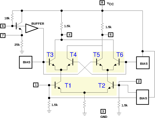
This process is repeated in the T3 and T4, as well as the T5 and T6 configurations. They will also distribute the common emitter current based on the base-to-emitter voltage relative to the other transistor. If the base-to-emitter voltage of T3 with respect to the base-to-emitter voltage of T4 is positive, more current will flow through the left collector resistor; otherwise, it will flow through the correct collector resistor. The same principle applies to T5 and T6, but in reverse, because their collectors are cross-connected with the collectors of T3 and T4.
Let's consider the voltage between the bases of T1 and T2 as one input (pins 1 and 2), and the voltage between the bases of T3 and T4 (and T5 and T6) as another input (pin 6). Then, we observe that if both inputs are positive, most of the current will flow through the collector resistor on the left side (through T1 and T3); similarly, if both inputs are negative (but through T2 and T6), this also occurs. However, if one input is negative and the other is positive, most of the current will flow through the collector resistor on the right side (through T1 and T4, or T2 and T5). The output of the circuit is the voltage between pins 4 and 5; whether this value is positive or negative depends on which collector has the largest current. Result: "+" and "+" result in "+"; "+" and "-" result in "-"; and so on: This is multiplication! If (at least) one input is 0, then both collector resistors will receive equal currents (due to the way T5 and T6 are connected across T3 and T4); this also works for multiplication. Unfortunately, this multiplication isn't very linear, as we will see later.
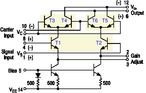
The figure shows another mixer chip, the MC1496. Here we can again see the same combination of six transistors. However, this chip is more basic than the NE602: users need to connect some resistors for DC biasing, and there is no pre-amplifier in front of T3...T6 (which can also be used as an oscillator in the NE602). On the other hand, the MC1496 does not have a simple emitter resistor, but instead has two current sources (the two transistors at the bottom), which users can connect a resistor between the emitters of T1 and T2.
Long tail for
Within the Gilbert cell mixer, we observe three copies of the same sub-circuit, each consisting of two transistors connected in a common-collector configuration. This sub-circuit is referred to as a "long tail pair," as shown in Figure (a). Let's now precisely calculate its function.
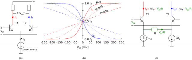
For typical transistors, the collector current is proportional to exp(VBE / 25 mV). In reality, this means that for every increase of 17 mV in VBE, the collector current doubles. Therefore, if the input voltage (applied between the two bases) is 17 mV, then the transistor on the left side needs to consume twice the collector current of the transistor on the right side. Their total remains I0, enforced by the current source. Thus, the transistor on the left side receives ⅔ I0, while the transistor on the right side receives ⅓ I0. Similarly, when the input voltage is 34 mV, the transistors receive 80% and 20% of I0 respectively. This is shown in Figure (b) by the solid line: clearly, the relationship between the input voltage and the two output currents is not linear. This also means that a Gilbert cell, which distributes current based on the "long tail," cannot operate linearly.
Figure (c) shows a variation of the "long tail" configuration, with a resistor R between the emitters. When V in is 0, there is no difference: the voltage across the resistor is 0 volts, so no current flows through it, and both emitter currents are ½ I 0. If V in is not 0, and we (for simplicity) assume that both BE voltages are constant (the well-known 0.6 volts), then the entire V in is located across the resistor. Since the current source insists on each current source drawing ½ I 0, the current V in / R must flow through the transistor: one transistor will have ½ I 0 + V in / R, and the other will have ½ I 0 - V in / R. The difference is exactly V in / R.
As mentioned earlier, this is done under the assumption of equal BE voltages. In reality, they will vary somewhat with changes in collector current, so the relationship will be slightly non-linear. See the dashed line in Figure (b): The larger R is, the more linear the relationship becomes, but the gain also decreases.
Now, we understand the function of the resistor connected between pins 2 and 3 of the MC1496: it allows the user to choose between higher linearity or higher gain. On the other hand, the NE602 uses a hard-wired connection to achieve maximum gain. In fact, this chip is known for its poor intermodulation performance (linearity). For both chips, the second input driving T3...T6 is non-linear; and the emitter resistor does not help with linearity.
Gilbert's multiplication device
Although the mixer circuit discussed above is called the "Gilbert cell," it was invented by Howard E. Jones [3]. Barry Gilbert is another inventor of a similar, but different, circuit. The AD534 is one of the earliest chips to use this circuit, and its internal schematic diagram is shown here. The circuits around T1...T6 look very similar to previous circuits, but the key difference is the addition of T7 and T8. These ensure that the second input of the mixer (through T9 and T10) is also linear.

To understand how Gilbert achieved this, we first need to examine another sub-circuit of the simulation chip technology, known as a "current mirror," as shown in Figure (a). This circuit contains two transistors; current I₁ is the input, and current I₂ is the output. The voltage at the base of the left-hand transistor stabilizes, causing its collector current to be I₁ (we are temporarily ignoring the base current). Because there is an exponential relationship between the base-emitter voltage and the collector current, the base voltage will be proportional to the logarithm of the input current. This same BE voltage is also the BE voltage of the right-hand transistor, and its collector current has an exponential relationship with it. The final result is that I₂ linearly depends on I₁, even though the transistors themselves are non-linear!
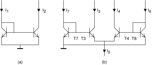
Inspired by the widely known current mirror, Gilbert proposed the circuit shown as (b). This is similar to two current mirrors, T7+T3 and T5+T8, except that not all emitters are connected together. The base-emitter-collector forms a loop, and careful observation reveals that the voltage across T7's BE minus the voltage across T3's BE must equal the voltage across T8's BE minus the voltage across T4's BE. Since there is an exponential relationship between the voltage across each transistor's BE and its collector current, we can conclude that I7 / I3 = I8 / I4. In other words, I7 : I8 = I3 : I4. Furthermore, we still have I3 + I4 = I0 (again, ignoring the base current). Now, if I0 comes from a current source (and therefore is constant), and we treat I7 and I8 as input signals, then this circuit will divide I0 by I3 and I4 in a ratio that is the same as I7 to I8. This can be written as: I3 = I0 * I7 / (I7 + I8). If I7 + I8 remains constant, then this is a very simple multiplication. However, it only applies to positive values (because transistors do not allow negative current).
To also handle negative numbers, we need more components, which is why we created the AD534 circuit diagram shown earlier. The components T3...T8 form a Gilbert multiplier. The combination of T1 and T2 with the emitter resistor creates a long-tailed pair to achieve good linearity, as do T9 and T10. They convert the input voltages V x and V y into a differential current; the difference between the two currents is the actual signal. Therefore, the input voltage V x determines the difference in the collector currents of T1 and T2. Next, as shown in the first diagram, the collector current of T1 is allocated to T3 and T4, and the collector current of T2 is allocated to T5 and T6; however, due to the presence of T7 and T8, this allocation now precisely relates to the ratio of the collector currents of T9 and T10 to the input voltage V y. (Note that, compared to Figure (b), T7 and T8 are "inverted," but they still have the same function.) Therefore, for both positive input voltages V x and negative input voltage V y, we achieve good linear multiplication.
For completeness: The four unlabeled transistors at the bottom of the AD534 circuit are again current sources, and an amplifier is constructed around operational amplifier A1 to convert the differential output current from T3...T6 into a non-differential output voltage.
Jones vs. Gilbert
Now we have the first image.(NE602)The circuit in the figure, invented by Jones but known as the "Gilbert unit," and the fourth diagram.(AD534)Gilbert invented the circuit, but it actually had no meaning. Name: The circuit looked very similar, so confusion was understandable. It seems that Gilbert invented his own circuit without knowing about the Jones circuit, and he tried to correct the naming; however, once a wrong name is widely used, it becomes difficult to change.
In applications such as the MC1496 and NE602 mixers, Jausen circuits are almost always used. The only advantage of Gilbert circuits is that they provide a linear response for the second input signal. For mixers, which are typically unnecessary. The second input signal is often used with a local oscillator, and if it has some distortion, harmonics will appear, which is usually not a problem. In fact, mixers are often intentionally designed to use square wave signals. For example, in diode ring mixers, the diodes act as switches that open and close based on the oscillating signal. This can also be done in a Gilbert cell (we will continue to use the name of the Jausen design): if a large AC voltage is applied between T3/T5 and T4/T6, these transistors will act as switches, sending the collector current from T1 and T2 completely to one or the other collector resistor.
More information about Barry Gilbert
As far as I know, besides his mixer circuit, people in electrical engineering don't have much knowledge of Jones. In contrast, Gilbert(1937-2020)With a long and successful career, he reflected on it in [5]. He began building televisions as early as his youth. While working at Big D, he became fascinated with oscilloscope technology, which led him to find a job at Tek where he also invented a multiplier circuit. Later, he worked as a chip designer for Analog Devices for many years.
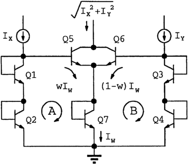
In Figure (b), we can see that he effectively uses the exponential relationship between current and voltage in a transistor to linearly amplify the current. (As an aside, this is similar to how a slide rule performs multiplication by adding distances.) He later generalized this idea and called it "the principle of cross-linearity." It can be used to design various circuits that perform mathematical operations on current and voltage. For example, the circuit shown here "calculates" the Pythagorean formula √(x² + y²).
His most significant contribution, at least in a literal sense, was the system used with the Tek 7000 series oscilloscope, which displayed settings (volts per division and microseconds) on the screen in both numerical and alphabetical form. In modern oscilloscopes, the screen is a computer display capable of showing any text. However, the 7000 series was still analog, featuring a cathode ray tube, where an electron beam was deflected horizontally and vertically to draw waveforms. Gilbert designed a set (analog!) of chips that could generate signals to control the electron beam in drawing numbers and letters on the screen [9]. At the time (around 1970), this was a huge luxury!

Is it outdated?
Both the designs by Jones and Gilbert can be traced back to the 1960s, while chips like the MC1496, NE/SA602/612, and SO42P were designed in the 1970s. It's clear that demand for such mixers has significantly decreased. This makes sense because today, people no longer use individual mixer chips but instead integrate entire receivers into a single chip, and/or perform much of the signal processing digitally. Production of the SO42P has already ceased. NXP (formerly Philips/Signetics) is the only manufacturer of the NE602 and its related products, and they have decided to stop production this year. They will still be available for some time, but eventually, the stock will run out.
The AD534, a four-quadrant multiplier, was introduced to the market in 1977. In 2006, it was displayed at the "Obsolete Analog Computing Technology" exhibition at the London Science Museum [11]. However, this was too early, as the chip was still being manufactured as of 2023. Clearly, there is still demand for this type of chip, but they are significantly more expensive than the mixers mentioned earlier.
I haven't yet found a truly good alternative to the NE602. People might think of the old MC1496, which is still manufactured, but it's not as easy to use: it requires higher power voltages and external DC biasing, and it doesn't have an internal oscillator. Alternatively, modern chips that operate in the GHz range typically come in small SMD packages that are unfriendly to hobbyists, and they also lack an internal oscillator.
Reference
[1] NE/SA602A datasheet, Philips, 1990.
[2] MC1496 datasheet, ON Semiconductor, 2006.
[3] Howard E. Jones: Dual-output synchronous detector using a transistor differential amplifier; U.S. Patent 3,241,078A (registered in 1963).
[4] Barrie Gilbert: A precise four-quadrant multiplier with nanosecond response time, IEEE Transactions on Solid-State Circuits, December 1968. Reprinted in [7].
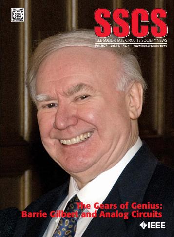
[5] Barry Gilbert: The brilliant gears, see [7].
[6] Thomas H. Lee: A Story of Continuity: The History of Second-Order Sampling in Analog Circuits, see [7].
[7] IEEE SSCS News, Fall 2007. https
https://sscs.ieee.org/images/files/newsletter_archive/sscs_newsletter_200710.pdf
[8] Barrie Gilbert: "Across Linear Circuits," Historical Overview. Analog Integrated Circuits and Signal Processing, 1996.
[9] Barrie Gilbert: Single-chip analog read-only memory for character generation, IEEE Solid-State Circuits Magazine, February 1971.
[10] https://www.nxp.com/ pcn/202208013DN
[11] James M. Bryant: Simulation Computing in the Digital Age. 2006. https https://www.analog.com/media/en/analog-dialogue/raqs/computation.pdf
 闽ICP备2021006864号-7
 闽公网安备35020602002794号